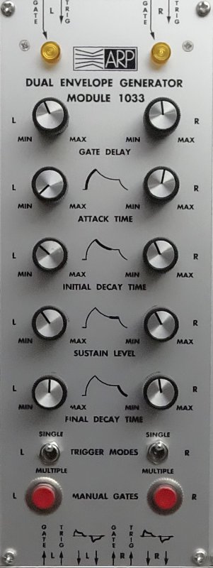
1033
Dual Envelope
The MOS-LAB 1033 contains two identical delayed-gate exponential envelope generators.
The 1033 Dual Delayed Gate Envelope Generator is usually used with voltage-controlled filters, amplifiers, and other modules requiring triggered control signals. For instance, when used with module 1006 FiltAmp, the 1033 Envelope Generator can be used to control the amplitude envelope or timbre variations of signals passing the FiltAmp with respect to time. The delayed-gate feature permits the user to delay the beginning of an envelope so that complex amplitude and timbre characteristics may be synthesized.
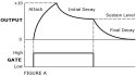
An exponential envelope generated by the 1033 Module may be defined by four adjustable parameters: Attack Time, Initial Decay Time, Sustain level, and Final Decay Time. The panel graphics emphasize the effects and use of each of these controls.
An envelope is initiated when appropriate signals are applied to the Gate and Trigger inputs. These inputs are accessible at both the upper and lower matrix switches, as shown on the panel graphics. In the Module 1033 the control signal which starts the envelope always passes through a delay circuit which allows the user to postpone the beginning of an attack from instantly from 3 milliseconds by adjusting the ”Gate Delay” panel control.
The operating mode of the envelope generator is determined by the switches labelled ”Trigger Modes”. When the ”Trigger Modes” switch is in the ”single” position, the Gate inputs are used to initiate an envelope; the Trigger inputs are not used. When the Gate signal is applied, the delay circuit is activated; after a time period selected by the front panel ”Delay Time” control, the delay circuit produces a pulse which initiates the attack. During the attack, the output of the envelope generator rises exponentially to 10 volts at a rate determined by the setting of the ”Attack Time” control. When the output of the envelope generator reaches 10 volts, the attack is ended and the output decays exponentially to the ”Sustain Level” at a rate determined by the ”Initial Decay Time” control. The sustain level is adjustable from 0 to 10 volts. The output remains at the sustain level until the Gate is removed. When the Gate is removed, the output immediately begins an exponential decay to 0 volts at a rate determined by the ”Final Decay Time” control (Fig. A).
If the Gate voltage is removed before the delay circuit has time to produce a pulse, the delay circuit will be reset immediately and will not produce a triggering pulse. Consequently, no envelope will be produced.
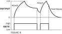
If the Gate voltage is removed during any part of the envelope cycle, the output of the envelope generator will always return directly to zero at the rate set by the ”Final Decay Time” control. Similarly, if the Gate voltage is reapplied before the output returns to zero, a new attack will begin after the time period specified by the ”Trigger Delay” control. The output need not return to zero before the initiation of a new attack (Fig. B).
When the ”Trigger Modes” switch is in the ”Multiple” position, the attack is initiated by a positive pulse at the ”Trig” input provided that a Gate signal is also present. In order to begin an attack, bot the Gate and the Trigger must be applied. The presence of a Gate signal or a Trigger pulse alone will not produce an attack. A new attack is generated each time a Trigger pulse is applied, and as long as a Gate signal is present. It should be noted that the Trigger input is connected to the input of the delay circuit which in turn triggers the attack. Therefore an attack can be generated if a Gate signal is present when the delay circuit produces its pulse which may be some time later than the initial trigger pulse.
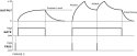
If the gate signal is applied in the absence of a trigger, the output voltage will rise to the sustain level at a rate determined by the setting of the ”Initial Decay Time” control. The output voltage will remain at the sustain level until the gate voltage is removed, at which time the output voltage will return to zero at a rate determined by the final decay control. (Fig. C).
TECHNICAL SPECIFICATIONS :
CONTROLS :
Attack Time: 0.001 secs to 2.0 secs
Initial Decay Time: 0.001 secs to 2.0 secs
Sustain Level: 0 to 10 volts.
Final Decay Time: 0.001 secs to 2.0 secs.
Delay Time: Instantly to 3.0 secs.
OUTPUTS :
0 to +10 volts.
0 to -10 volts.