


1036
S H / Random Voltage
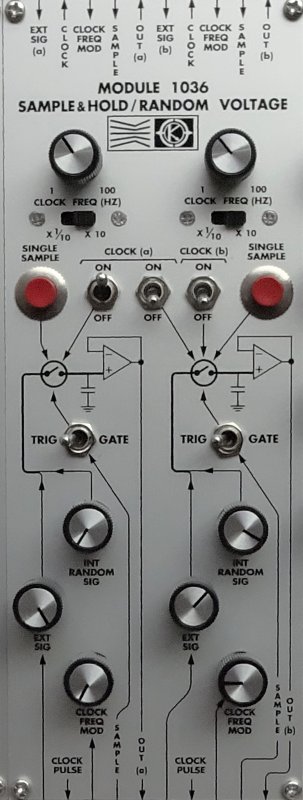
The MOS-LAB 1036 Dual Sample & Hold / Random Voltage module contains two sample and hold circuits, two random noise generators, and two voltage controlled pulse generators. The 1036 is usually used in conjunction with voltage controlled oscillators to produce random tone sequences, scales, arpeggios and programmed melodic patterns. The module can also be used to control voltage controlled filters, amplifiers, etc.
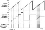
A sample and hold circuit has a signal input, a signal output, and a sample command input. When a pulse is applied to the sample command input, the output signal voltage immediately assumes the same value as the input signal voltage. After the sample command pulse, the output signal vill hold at that same level until anther sample command pulse is applied. During the holding period between pulses, the input signal has no effect on the output signal. In the case shown in Figure A, a sawtooth waveform is applied from an external oscillator to the ”Ext Sig” input of a 1036 sample and hold. Sample command pulses can be generated by pushing the ”Single Sample” button, applying an external pulse (as from an oscillator or keyboard trigger) to the ”Sample” input (with the ”Trig/Gate” switch set to ”Trig”), or by using an internal clock pulse generator.
There are two separate clock pulse generators. The frequencies of the clock pulse generators are determined by the front panel ”Clock Freq” knobs and range switches. An external signal applied to the ”Clock Freq Mod” inputs will also affect clock frequency. Clock (a) can be used to provide sample command pulses to both the (a) and (b) sample and hold circuits. Of the three toggle switches between the ”Single Sample” buttons, two are connected to clock (a). The switch on the left connects clock (a) to sample and hold (a) while the center switch connects clock (a) to the sample and hold circuit (b). The right hand switch connects clock (b) to sample and hold (b).
The ”Clock Pulse” output is a 10 volt pulse that corresponds to the sample period of any sample command pulse reaching the sample and hold circuit. The internal clock, the ”Single Sample” button, or external pulses all produce pulses at the ”Clock Pulse” output. Usually the pulse can be used to trigger envelope generators, sequencers, and so forth.
Any external signal which one desires to sample must be applied to the ”Ext Sig” inputs. The knobs associated with the ”Ext Sig” inputs are used to attenuate the incoming signal.
The output voltage from the sample and hold circuit will usually be a series of steps or discrete voltages. The output signal shown in Figure A is typical. Normally this output signal is used to control voltage controlled oscillators, filters, amplifiers, and so forth. If a waveform is sampled at a high enough frequency, however, the output signal can be used as and audio source.
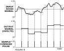
In addition to sampling external signals, the module 1036 has built-in random signal generators. By advancing the front panel knobs labelled ”Int Random Sig”, noise can be applied to the signal input of the sample and hold circuits. When this random signal is sampled by the application of a sample command pulse, the output signal is a series of stepwise random voltages, as shown in Figure B. If an external signal is also applied, the random signal and the external signal will be mixed internally before being sampled.
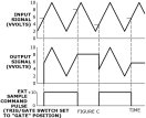
When an external sample command pulse (as from an oscillator) is applied to the ”Sample” input, two different results can be selected by the ”Trig / Gate” switch. In the ”Trig” position, the input pulse is differentiated and the leading or positive going edge of the external pulse triggers the sampling circuit. When the ”Trig / Gate” switch is in the ”Gate” position, the output signal of the sample and hold circuit will track the input signal as long as the external sample command pulse is positive. As soon as the pulse ends and the voltage at the ”Sample” input returns to zero, the sample and hold circuit will store and hold the last value of the input signal before the sample command pulse returned to zero. Figure C shows an example; when the sample command pulse is high, the output signal tracks the triangle wave at the signal input. When the sample pulse goes to zero volts, the output signal holds at the voltage which was present when the sample command pulse dropped to zero.
&